Common modules for embedded development: the principle and application of digital tubes
“Nixie tube, also called glow tube, is an Electronic device that can Display numbers and other information. The glass tube includes an anode and multiple cathodes made of wire mesh. The shape of the cathode of most digital tubes is a number. The tube is filled with low-pressure gas, usually mostly neon plus some mercury and/or argon. Charge a certain cathode, the digital tube will emit color light, depending on the gas in the tube, generally orange or green.
“
Nixie tube, also called glow tube, is an electronic device that can display numbers and other information. The glass tube includes an anode and multiple cathodes made of wire mesh. The shape of the cathode of most digital tubes is a number. The tube is filled with low-pressure gas, usually mostly neon plus some mercury and/or argon. Charge a certain cathode, the digital tube will emit color light, depending on the gas in the tube, generally orange or green.
The most common form of digital tube has 10 cathodes, and the shapes are numbers 0 to 9. Some digital tubes also have one or two decimal points. However, there are other types of digital tubes that display letters, signs, and symbols. For example, a “digital tube” whose cathode is a mask made of a template with holes in the shape of numbers.
A 170 volt DC voltage is applied between the cathode and the anode, and each cathode can emit neon red-orange light. Due to the difference of the mixed gas, the colors of different types of digital tubes are different. The longer-life nixie tubes are manufactured with mercury added to reduce sputtering, and the color of the light emitted is blue or purple. In some cases, these colors are filtered by the red or orange filter coating on the glass.
How does the digital tube form the numbers 0 to 9?
The nixie tube is also called 8-segment LED light, which is composed of 8-segment LED light.
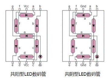
In our actual application, the 8 segments of LED lights are named: a, b, c, d, e, f, g, h (or dp)
Inside the nixie tube, the nixie tube is divided into a common cathode nixie tube and a common anode nixie tube according to the connection.
Common anode digital tube: the anodes of 8 LED lights are all connected together, and the cathodes of each LED light are led out separately;
Common cathode digital tube: the cathodes of 8 LED lights are all connected together, and the anode of each LED light is led out separately;
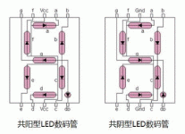
The left side of the figure below is the internal structure of the common anode digital tube, and the right is the internal structure of the common cathode digital tube.

The common end of the common anode digital tube is connected to high level, one end is connected to low level, and this segment is on; the common cathode digital tube is common end connected to low level, and one end is connected to high level, and this section is on. The logic of the two is just the opposite. .
Digital tube drive display
Generally speaking, for the digital tube to display normally, it is necessary to use a drive circuit to drive each segment of the digital tube to display the number we want. Therefore, according to the different driving methods of the digital tube, it can be divided into static and dynamic Two types.
1. Static display driver
Static drive is also called DC drive. Static drive means that each segment code of each nixie tube is driven by an I/O port of a single-chip microcomputer, or driven by decoding with a two-decimal decoder such as a BCD code. The advantage of static driving is simple programming and high display brightness. The disadvantage is that it occupies many I/O ports. For example, driving 5 digital tube static display requires 5×8=40 I/O ports to drive. You must know that an 89S51 single-chip microcomputer is available. There are only 32 I/O ports. In actual application, a decoder driver must be added to drive, which increases the complexity of the hardware circuit.
2. Dynamic display driver
The digital tube dynamic display interface is one of the most widely used display methods in the single-chip microcomputer. The dynamic drive is to combine all the 8 display strokes of the digital tube “a, b, c, d, e, f, g, dp” with the same name In addition, a bit gating control circuit is added to the common pole COM of each nixie tube. The bit gating is controlled by each independent I/O line. When the single-chip microcomputer outputs the font code, all the nixie tubes receive the same The font code, but which digital tube will display the font depends on the microcontroller’s control of the bit strobe COM circuit, so we only need to turn on the strobe control of the digital tube that needs to be displayed, and the bit will display the font. The strobed nixie tube will not light up. By controlling the COM terminal of each nixie tube in turn by time-sharing, each nixie tube is controlled and displayed in turn, which is a dynamic drive. In the alternate display process, the lighting time of each digital tube is 1~2ms. Due to the persistence of human vision and the afterglow effect of light-emitting diodes, although the digital tubes are not actually lit at the same time, as long as the scanning speed is sufficient Fast, it gives the impression that a set of stable display data will not flicker. The effect of dynamic display is the same as that of static display, which can save a lot of I/O ports, and the power consumption is lower.
The Links: PHT4008 NL128102BC28-07


